
Florida Metal Roof Drainage: Scuppers, Gutters, Overflow
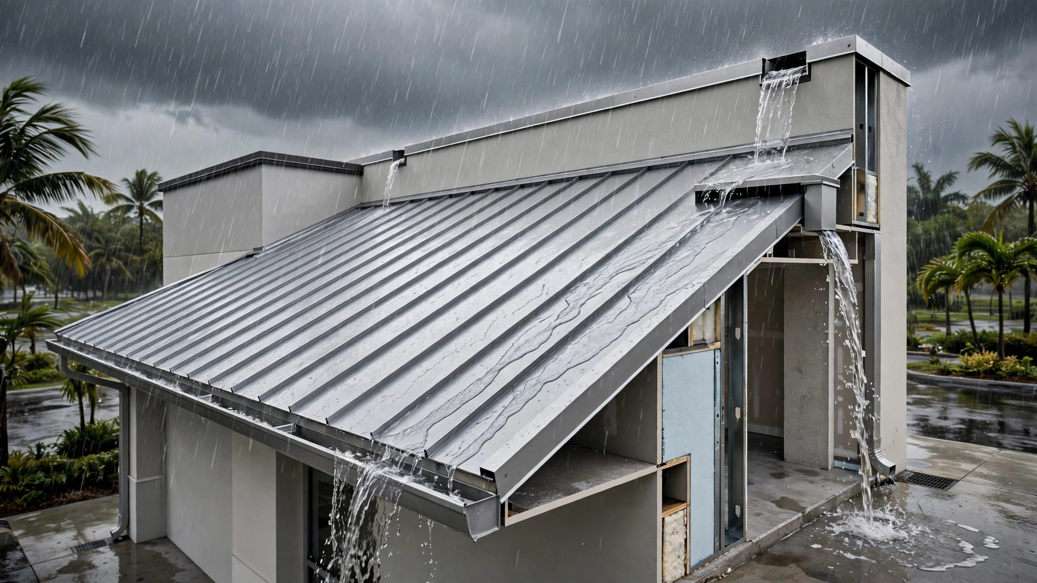
Good Florida metal roof drainage keeps heavy rain moving before it can test seams, fasteners, flashings, and the roof structure. A system that works during a light shower may still pond during a short, intense Florida storm.
The right design connects roof slope, primary drainage, gutters or scuppers, and an independent emergency overflow path. Final sizing, structural details, wind uplift, product approvals, and code compliance must be checked for the specific building and jurisdiction.
How Florida Metal Roof Drainage Works
Roof drainage starts with the shape of the roof. Water should move toward an edge, gutter, scupper, or roof drain without collecting around penetrations or low points.
Primary drainage carries ordinary runoff
Primary drainage is the route intended to handle normal rainfall. On a sloped metal roof, that route may lead to the eave and gutter. A parapet roof may use scuppers through the wall. A roof with internal low points may need roof drains connected to conductors or leaders.
The Florida Building Code requires drainage at low points when the roof doesn't slope toward an edge. The design must account for the roof area feeding each outlet, the roof slope, rainfall conditions, and the discharge location.
Standing seam, PBR/R, AG or Multi-Rib, and 5V panels can shed water differently. Panel profile, seam direction, trim, and installation details all affect how quickly runoff reaches the selected drainage point.
Emergency overflow protects the building
Secondary drainage provides another exit when a primary drain, gutter, or scupper becomes blocked. Leaves, palm debris, dirt, roof grit, and storm-borne material can restrict a drainage opening quickly.
The overflow path should release water before it rises high enough to enter wall assemblies or load the roof structure excessively. It must discharge to an approved location and should not depend on the primary roof-drain line.
An overflow opening is not a substitute for a correctly sized primary system. It is a separate defense against blocked or backed-up drainage.
Scuppers, Gutters, and Roof Drains
The best drainage component depends on the roof geometry and the way water leaves the building. A low-slope roof with a parapet needs a different plan from a sloped residential roof with open eaves.
When scuppers make sense
A scupper is an opening through a parapet or exterior wall. It gives water a direct route off the roof, often into a conductor head, downspout, or open discharge area.
Primary scuppers are normally placed at the low side of a roof section. Their flashing must direct water through the wall while protecting the metal roof, wall framing, and parapet cap. Review the parapet scupper flashing installation before selecting a profile or opening location.
A scupper that is too small, poorly sealed, or placed above the actual low point can leave water trapped on the roof. The opening also needs enough clearance for debris and inspection.
When gutters or drains are better
Gutters collect runoff along the eave and send it through downspouts to an approved discharge point. A properly shaped eave edge helps prevent water from running behind the gutter or staining the fascia. See this guide to choosing an eave drip edge for metal roofing when coordinating panels, fascia, and gutter geometry.
Roof drains suit low-slope sections with internal low points or parapets that prevent water from flowing over the edge. The Florida Plumbing Code and ASCE 7, Chapter 8 with commentary, provide the framework for sizing and discharge. The calculation must use the actual contributing roof area and project conditions.
Florida Overflow Scupper Requirements
Overflow details need careful elevation control. A small difference in height can decide whether water reaches the emergency path before it reaches vulnerable wall or roof components.
Set the overflow above the finished roof
Under the Florida code provisions summarized in the project research, an overflow scupper is installed at least 2 inches and no more than 4 inches above the finished roof covering. Plumbing code language also places the inlet flow line 2 to 4 inches above the low point of the finished roofing surface, excluding sumps.
That measurement applies to the completed roof surface, not simply the structural deck. Include the panel profile, insulation, tapered components, membrane layers, and other materials that change the finished elevation.
The primary drain or scupper must remain lower so ordinary runoff reaches it first. However, the overflow cannot sit so high that water rises into parapet construction or penetrations before escaping.
Size and place the opening for real flow
Overflow scuppers must be at least 4 inches in any dimension under the cited code provisions. That minimum does not establish the correct size for every roof. Required capacity still depends on rainfall, roof area, opening configuration, and the amount of water the primary system could otherwise carry.
Overflow openings should be located as close as practical to required leaders, conductors, downspouts, or wall and parapet scuppers. Keep the path visible and free of trim, coping, equipment, or sealant that could restrict flow.
Do not count primary drainage flow when sizing secondary overflow scuppers or drains. The emergency route must work on its own if the primary path is blocked.
Roof Slope, Panel Layout, and Ponding
Low-slope metal roofs depend on positive drainage. A roof can appear nearly flat from the ground while still having enough slope for its selected panel system. Problems begin when the slope is too shallow, the roof settles, or framing and insulation create a recurring low spot.
Review the Florida standing seam height guide before ordering panels. Seam height helps form the water-shedding profile, but it doesn't replace the slope and drainage plan.
The Residential Code includes a 3:12 minimum slope for lapped, nonsoldered-seam metal roofs without applied lap sealant. That is a roof-covering requirement, not a universal slope for every metal panel, gutter, scupper, or drain. The selected manufacturer system and project approval may require different conditions.
Ponding usually comes from more than one issue. A blocked gutter, uneven deck, rooftop curb, valley, or failed flashing can slow the water path. Water may then remain near seams, fasteners, or cut edges. Repeated ponding can leave staining, coating wear, corrosion, interior leaks, or added structural load.
A small puddle after a storm isn't automatically a failure. A recurring puddle that remains after ordinary rain deserves inspection, especially when it appears beside a penetration or returns in the same location.
Flashing, Openings, and Wind-Resistant Details
Drainage works only when the surrounding metalwork supports it. Water can reach the correct outlet and still enter the building through a weak transition.
Coordinate trim with movement and runoff
Standing seam panels expand and contract. Eave cleats, receiver details, closures, and flashing must hold the edge securely without pinning the panel in a way that creates stress. Read the guidance on Florida standing seam eave cleat installation when the eave feeds a gutter or directs water away from the fascia.
Flashing should create a shaped water path. Sealant supports a properly lapped detail, but it shouldn't be the only barrier against wind-driven rain. Use compatible metals, fasteners, closures, and sealants for the selected panel and exposure.
Valleys, dead valleys, roof-to-wall transitions, and changes in slope need the same attention. A valley that ends above a gutter must discharge cleanly without gaps or backflow. Debris trapped in a valley can slow water and keep the surrounding metal wet.
Protect penetrations and rooftop equipment
HVAC curbs, vents, skylights, and pipe penetrations interrupt the natural flow of water. A curb can create a ponding area upslope if its flashing doesn't split or redirect runoff. On commercial roofs, several nearby penetrations can combine into one difficult drainage zone.
A raised curb, correctly lapped flashing, and an upslope water-splitting detail may be necessary. The profile of the metal roof matters, so flashing roof curbs around metal roof openings should be coordinated with the exact panel system.
Wind uplift adds another design requirement. Trim, scuppers, coping, gutters, clips, and fasteners must attach to the approved substrate and match the tested assembly. A drainage opening that works hydraulically can still fail if wind pulls the surrounding metal loose.
What Florida Permit Drawings Should Show
A drainage plan should allow the contractor, designer, reviewer, and inspector to follow the water path. A roof plan that shows only panel lines and gutters leaves important questions unanswered.
Include the following information where applicable:
- Roof slopes, high points, low points, valleys, sumps, and drainage arrows.
- Contributing roof areas for each drain, scupper, gutter, and downspout.
- Primary drainage locations and the route to an approved discharge point.
- Overflow scupper or drain locations, elevations, dimensions, and discharge paths.
- Finished roof elevations used to set the 2 to 4-inch overflow height.
- Parapet, coping, conductor head, downspout, gutter, and eave flashing details.
- Panel profile, seam or lap direction, underlayment, closures, sealants, and attachment method.
- Rooftop equipment, curbs, penetrations, crickets, valleys, and areas where runoff changes direction.
Florida's current code set is the Florida Building Code, 8th Edition (2023). Local amendments, project occupancy, flood conditions, coastal exposure, and high-wind requirements can affect the final design. Miami-Dade and Broward projects may also fall within the High-Velocity Hurricane Zone.
The panel, clip, fastener, trim, substrate, and tested pressures must match the selected approval. Review Florida metal roof product approvals before fabrication or ordering. The building official, licensed design professional, or responsible contractor should verify the complete permit package.
Key Takeaways
- Primary drainage moves ordinary rain to gutters, scuppers, roof drains, or roof edges.
- Emergency overflow provides an independent escape route when primary drainage backs up.
- Florida overflow scuppers are generally set 2 to 4 inches above the finished roof covering under the cited code provisions.
- An overflow opening must be at least 4 inches in any dimension, but project capacity still requires calculation.
- Roof slope, panel profile, trim, valleys, and penetrations must work as one drainage system.
- Gutter, scupper, drain, leader, and overflow sizing depends on the building and jurisdiction.
- Wind uplift, approved attachment, corrosion exposure, and discharge location belong in the final review.
Florida Metal Roof Drainage FAQ
Does every Florida metal roof need scuppers?
No. A sloped roof may drain over its edges into gutters or directly to an approved location. Scuppers are common where parapets or exterior walls control the roof edge. The roof design determines whether a scupper, gutter, drain, or combination is appropriate.
Are overflow scuppers connected to primary drains?
They should provide a separate emergency route. The overflow must discharge to an approved location and cannot depend on a blocked primary drain line. The final connection and discharge detail must follow the applicable Florida code and project drawings.
What causes ponding on a low-slope metal roof?
Common causes include inadequate slope, settlement, deflection, clogged outlets, blocked valleys, poorly detailed curbs, and flashing that redirects water into a low area. Wind-blown debris and rooftop equipment can make the problem worse during heavy rain.
Can a contractor choose a scupper size from a standard chart?
A minimum opening requirement doesn't provide the full design. The contractor or designer must consider rainfall, contributing area, roof geometry, outlet configuration, finished elevations, and the required primary and secondary capacity. Verify the calculation with the project professional and local building department.
Conclusion
Florida metal roof drainage depends on a complete water path, not one oversized gutter or a bead of sealant. Roof slope, panel layout, flashing, primary outlets, and overflow openings must work together before the next heavy storm arrives.
The safest plan identifies where ordinary runoff goes, where emergency water goes, and what happens when debris blocks the first route. Final dimensions, attachment, wind uplift, product approval, and code compliance belong to the specific building and jurisdiction.
Share Our Metal Roofing News Articles
Related Posts