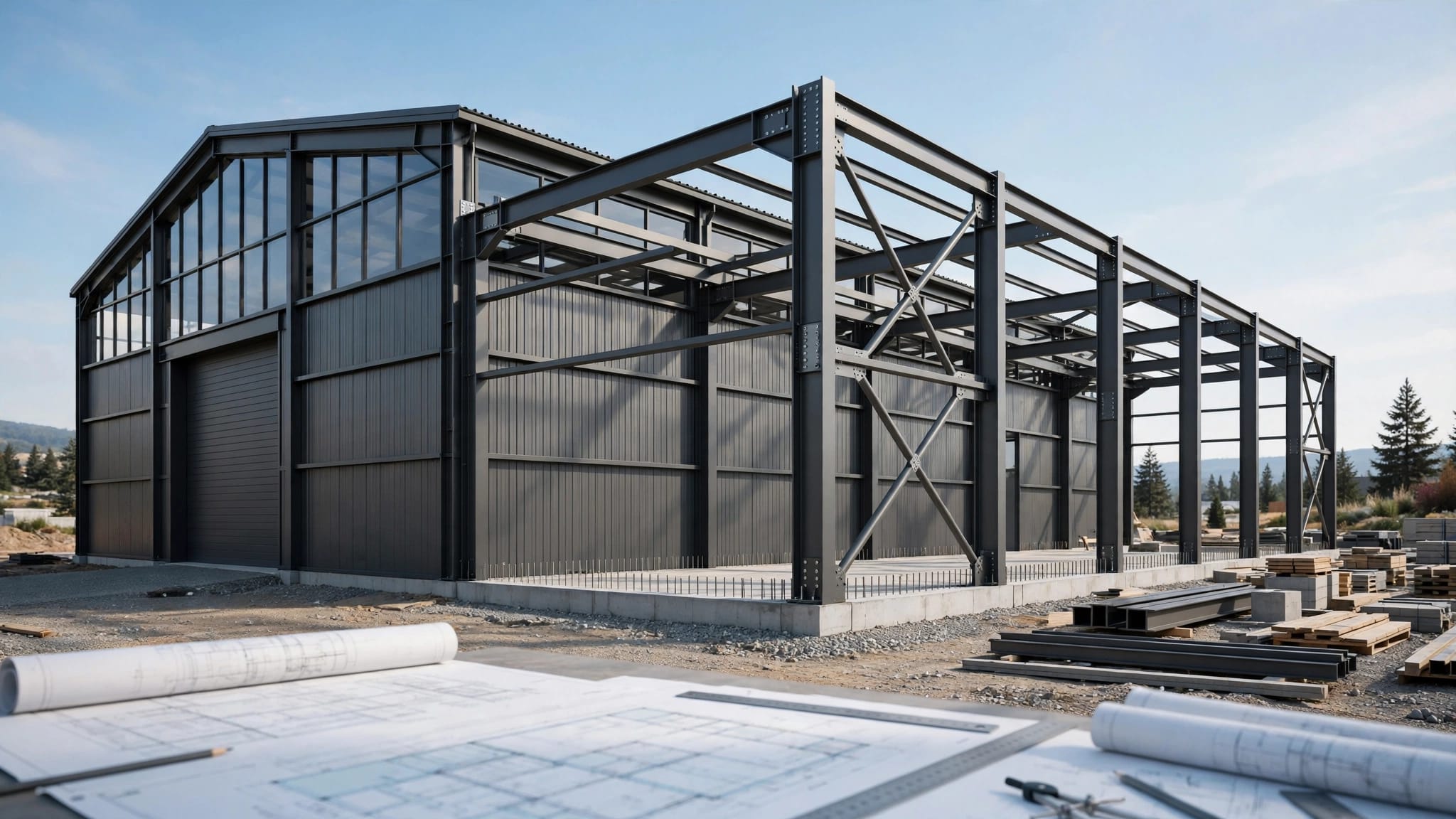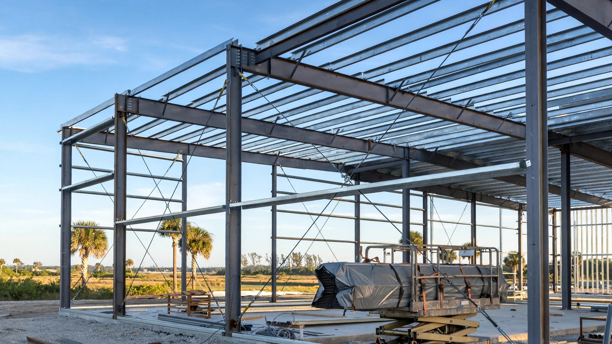
How to Read Steel Building Erection Drawings
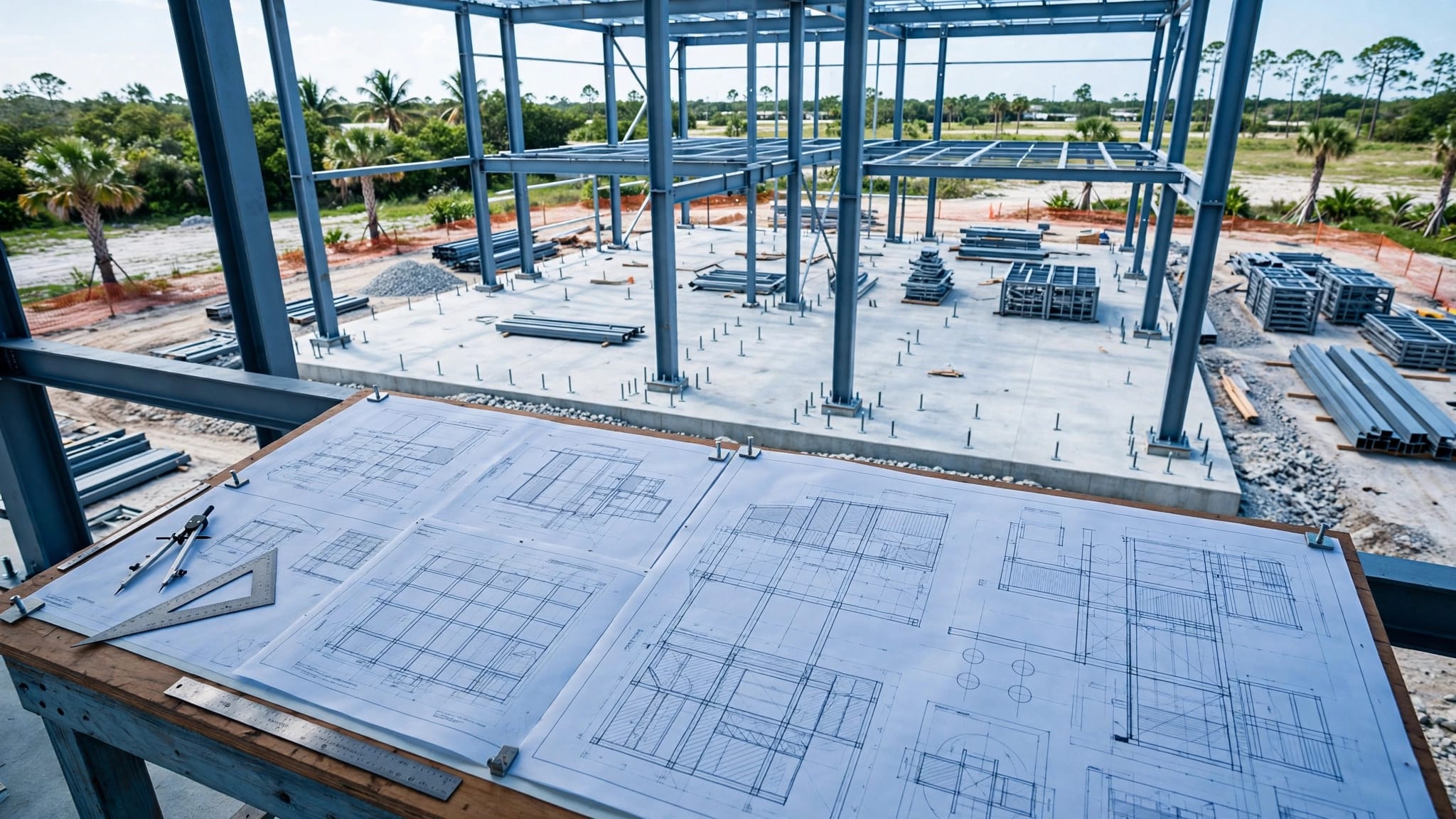
A misplaced anchor bolt can interrupt your steel building project before the first frame goes up. Reading steel building erection drawings starts with the approved set and checking how locations, dimensions, and details connect.
For a Florida garage, workshop, or agricultural building, those checks also help prevent roofing materials from arriving with incorrect lengths or attachment details. Begin with the drawing package's approval status, then follow the layout into the framing and connection sheets.
Start with approved steel building erection drawings
Check the title blocks and revisions
Read each sheet's title block before using its details. Confirm the project name, building identification, sheet number, issue date, revision, and release status.
A newer date alone doesn't prove a sheet is approved for construction. Check the issue description and project document records. Revision clouds may highlight changes, but the revision history and accompanying instructions establish what changed.
Keep superseded sheets out of the working set. Also check whether a revision affects related sheets, material lists, anchor locations, or previously ordered components.
Use the sheet index as your map
The sheet index identifies the drawings included in the package. Suppliers organize their sets differently, so don't assume a particular sheet number always contains the same information.
Locate the general notes, anchor-bolt layout, framing plans, elevations, sections, connection details, and panel layouts. Then identify any separate erection instructions or component schedules.
Mid Florida Metal Roofing Supply's construction packages include information about framing, anchor placement, door and window spacing, and panel layout. Use the package issued for your building, alongside the approved foundation and roofing documents.
Locate grids, dimensions, and elevations
Follow grid lines and bay spacing
Grid lines establish reference locations across the building. Letters and numbers commonly identify them, but the drawing legend controls their meaning.
Find the building orientation first. Then locate column lines, endwalls, sidewalls, and framed openings. A bay is the space between adjacent framing lines; confirm each bay dimension rather than assuming equal spacing.
Read what each dimension measures. Column centerlines, outside steel faces, and finished wall surfaces can define different distances. Compare individual bay dimensions with the overall dimension, and refer any disagreement to the project team.
Separate elevation views from elevation values
An elevation view shows a vertical face of the building. An elevation value identifies a height relative to a stated reference, or datum.
Read wall elevations alongside the floor plan to locate doors, windows, wall girts, and bracing. Sections show relationships that a face view may hide, including roof slope and framing depth.
Check whether eave height refers to framing, finished roofing, or another defined point. Similarly, follow the specified datum for column bases and floor levels. Use written dimensions rather than measuring a printed or onscreen drawing, even when a scale appears.
Read the anchor-bolt plan with foundation drawings
The anchor-bolt plan locates the anchors that connect column bases to the foundation. Follow the grid references, bolt-group dimensions, and base-plate orientation.
Check the specified anchor diameter, spacing, projection, and any details referenced elsewhere. Projection is the length extending above the stated surface. Don't confuse it with embedment into the concrete.
Coordinate these requirements with the approved foundation drawings. The building supplier's anchor layout doesn't necessarily provide the complete footing design, reinforcing details, or foundation specifications.
Before concrete placement, compare the layout with column base details and the project survey references. After placement, verify actual locations against the required dimensions and tolerances.
If anchors don't match, document the condition and request direction from the project engineer or building supplier. Don't bend anchors, enlarge base-plate holes, or relocate steel based on a field assumption. The appropriate correction requires project-specific review.
Match member marks to framing locations
Identify primary framing
Primary framing generally includes the columns and rafters that form the main frames. Member marks connect individual pieces to their locations, schedules, and assembly details.
Match the identification on delivered steel to the erection drawing and shipping documentation. Then confirm the member's grid location, orientation, and connection references.
Similar-looking pieces aren't automatically interchangeable. Hole patterns, plate arrangements, and connection geometry may differ. Check splice locations and any left-hand or right-hand designation before positioning a member. If a mark is missing or unreadable, ask the supplier to identify the piece.
Trace secondary framing and bracing
Purlins support roof panels, girts support wall panels, and eave struts sit along the roof-to-wall junction. Their drawings show spacing, orientation, laps, and connections.
Follow each member mark into its supporting detail. Check flange direction and lap arrangements rather than relying on how a loose component looks.
Also identify bridging, sag rods, and other specified restraints. Purlin bracing and roof panel support require separate checks. Bridging doesn't make an unsupported panel span acceptable, and a different roofing panel doesn't automatically eliminate a framing restraint.
Decode abbreviations and detail callouts
The drawing legend takes priority over general conventions. These abbreviations are common, but confirm their meanings in your package.
| Abbreviation | Common meaning |
|---|---|
| CL or C/L | Centerline |
| EL or ELEV | Elevation |
| AFF | Above finished floor |
| TYP | Typical |
| EQ | Equal |
| NTS | Not to scale |
| UNO | Unless noted otherwise |
Treat these as reading aids, not project specifications. For example, "TYP" applies only to the conditions covered by that note or detail.
Detail callouts direct you to enlarged information. A reference commonly combines a detail identifier with a sheet identifier. Find both, then check that the detail applies to the member and location you're reviewing.
Section arrows indicate the viewing direction for a cut through the building. Grid bubbles identify reference lines, while elevation symbols identify heights or datums.
Weld symbols carry fabrication or field-welding requirements. If you can't interpret one confidently, request clarification rather than assuming weld size, length, or location.
Follow connection details and erection requirements
Read the complete connection requirement
Connection details show how members fit together. Trace the drawing's notes and references for plates, bolts, holes, washers, welds, and member orientation.
Check bolt diameter, grade, length, quantity, and installation requirements wherever the documents specify them. A bolt count alone doesn't identify the complete connection.
Don't substitute a general torque value for the project's required installation method. Likewise, a generic detail may have exceptions identified in a schedule or location-specific note. Confirm those exceptions before assembly.
If steel doesn't fit as detailed, pause the affected work and request direction before cutting, drilling, or welding.
Find the sequence and temporary stability instructions
Locate the supplier's erection instructions and any project-specific sequence or bracing requirements. Drawing sheet order isn't an erection sequence.
Identify when the documents require temporary bracing, permanent bracing, and framing checks. Don't assume a partly assembled frame can stand safely because its final configuration appears stable.
A drawing that shows permanent bracing doesn't, by itself, establish temporary stability during erection.
Coordinate the drawings with the contractor's erection plan, lifting procedures, fall protection, and site safety requirements. Where instructions are missing or unclear, obtain direction from the responsible project parties before proceeding.
Coordinate framing with roof-panel drawings
Check geometry before releasing materials
The structural frame dimensions may differ from finished roofing dimensions. Overhangs, panel extensions, trim, and roof slope affect panel lengths and interfaces.
Compare the erection package with roof-panel shop drawings before fabrication. Review eaves, rakes, ridges, penetrations, and transitions. Metal roofing shop drawing review helps identify mismatches before panels are cut and flashing is formed.
Before installation, check the building's square, roof plane, and supporting framing against project requirements. In particular, verify framing alignment before roofing so the eave condition matches the intended panel layout.
Match the panel system and approved assembly
PBR, R, Multi-Rib, and standing seam systems can have different support and attachment requirements. Match the selected panel to its specified substrate, support spacing, clips or screws, and installation details.
For Florida projects, coordinate the roof documentation with the project's wind criteria and applicable approval conditions. Roof panel approvals and installation details must describe the assembly being installed.
On conditioned buildings, also check insulation, air-sealing details, roof finish, and the permitted assembly. A panel's appearance or product name doesn't establish compliance for the complete roof.
Resolve discrepancies before proceeding
Cross-check steel building erection drawings whenever one sheet depends on another. An opening on a wall elevation should agree with its framing detail. Likewise, an anchor group should match the corresponding column base.
When something conflicts, record the sheet numbers, revisions, grid location, member mark, and disputed dimensions. Include field measurements and photographs when relevant.
Send a request for information, often called an RFI , through the project's established process to the engineer or building supplier. Ask for a clear written resolution and any revised documents needed.
Hold the affected fabrication or installation until the responsible party resolves the issue. Verbal assumptions can leave crews, suppliers, and inspectors working from different requirements.
Key Takeaways
- Confirm the approved issue and revision of every sheet before using its information.
- Follow grid locations and member marks through the related plans, schedules, and connection details.
- Coordinate anchor layouts with foundation documents and framing layouts with roof-panel requirements.
- Refer conflicting dimensions, missing instructions, and proposed field changes to the project engineer or building supplier.
Frequently Asked Questions
Are erection drawings the same as fabrication drawings?
They have different purposes. Erection drawings show where components belong and how they assemble. Fabrication drawings provide manufacturing information for individual components.
Some packages combine information, so check the sheet titles and notes. Use the documents approved for the task rather than assuming one drawing type contains every required detail.
Can I calculate missing dimensions from the drawing scale?
Don't use scale measurements to establish missing construction dimensions. Printing, scanning, and screen zoom can change the apparent size.
Request the missing dimension from the project engineer or supplier. Although adding clearly stated dimensions can help you cross-check a layout, an unresolved or conflicting dimension still needs written clarification.
Keep Every Check Tied to the Approved Set
Reliable drawing review connects each component's location with its dimensions, connection details, and related project documents. That habit helps catch an anchor mismatch or roofing interface problem before it becomes a field correction.
Keep the approved drawings available to everyone responsible for the work. Use this guide to understand the package, while following project-specific erection instructions and site safety procedures.
Share Our Metal Roofing News Articles
Related Posts