Metal Roofing Shop Drawings to Verify Before Fabrication
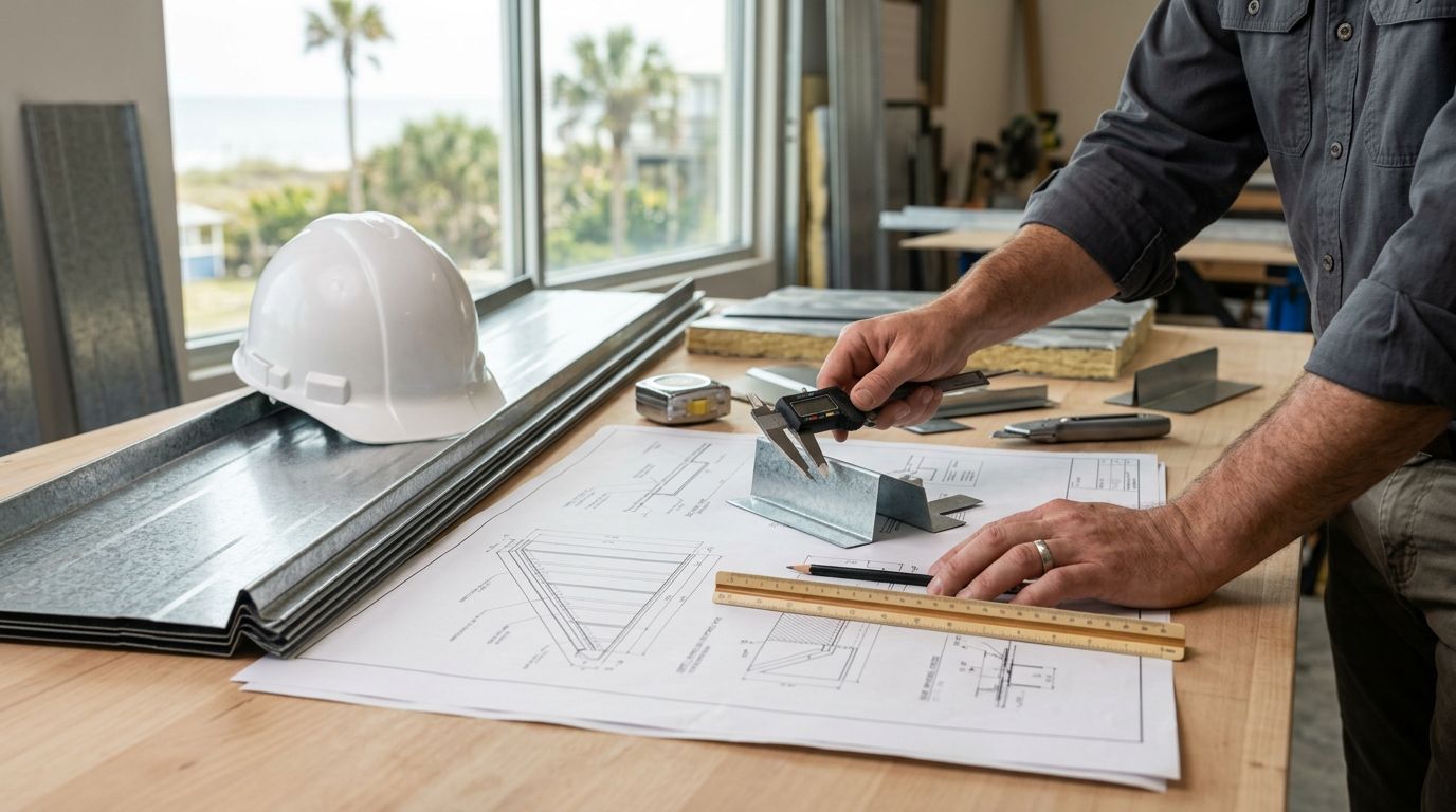
A metal roof can look simple from the ground, yet a missed detail on paper can cause wasted panels, leaks, or a failed inspection. Metal roofing shop drawings turn plans and specifications into fabrication instructions, so they need a hard review before coils are cut and trim is formed.
For Florida projects, the review also ties directly to wind resistance, product approval limits, and drainage details. A disciplined release process protects the contractor, fabricator, owner, and installer from expensive field fixes.
Start With a Fabrication Release Baseline
Shop drawings should match the latest architectural, structural, and roof plans before anyone confirms material lengths. Begin by comparing drawing titles, dates, revision numbers, scale, roof elevations, and sheet references.
The 2023 Florida Building Code took effect on December 31, 2023. Product approvals, attachment details, and design calculations must align with the code edition and the approved roof assembly.
Confirm roof geometry and dimensions
Verify roof slope, eave-to-ridge dimensions, hips, valleys, parapet heights, and changes in deck elevation. Dimensions taken from a reflected roof plan may differ from structural framing dimensions, especially around framed openings and additions.
Check the panel run in the direction of water flow. A standing seam panel that reaches from eave to ridge may avoid end laps. However, a low-slope or long roof can require a manufacturer-approved lap or expansion approach.
Also compare field measurements to the drawings when the existing structure is irregular. Metal panels don't forgive a roof that runs out of square.
Lock down revisions before material release
Every drawing package needs a visible revision date and a clear status. "For review," "approved as noted," and "released for fabrication" are different stages.
Maintain one current panel layout, one trim schedule, and one detail set. If a field change moves a vent, adds a curb, or changes a roof edge, send it back through the same revision path. McElroy Metal states that erection drawings control when they conflict with installation manuals, which makes the final issued drawing set especially important.
Fabricating from an outdated roof plan can create panels that fit the original drawing but fail at the actual penetrations, edges, or drainage points.
Verify Metal Roofing Shop Drawings for Panel Layout
The roof plan should identify every panel type, profile, width, gauge, finish, color, and length. It should also show the panel start point and the direction each panel runs.
A layout is more than a count of panels. It shows where the system begins, terminates, transitions, and handles roof geometry.
Match the panel profile to the approved system
Confirm that the specified profile matches the product approval and the project documents. Florida projects may use AG or Multi-Rib, PBR/R, 5V, exposed-fastener panels, or standing seam systems. Each profile has different sidelaps, ribs, closures, flashing shapes, and attachment rules.
Don't substitute a similar-looking profile because its coverage width appears close. A change in rib height or seam geometry can affect uplift capacity, trim fit, and water management.
Panel orientation also needs review. Ribs should run down the roof slope unless the approved design shows another configuration. Check layouts at dormers, porch tie-ins, shed roofs, and roof-to-wall transitions where the orientation can shift.
Review seams, endlaps, and cut-panel locations
Mark sidelap direction, seam engagement, sealant placement, and any field-seaming requirements. For exposed-fastener panels, show stitch screw locations where the manufacturer requires them. For standing seam systems, identify the seam type and whether it snaps, mechanically locks, or uses a batten cap.
Avoid placing narrow cut panels where they are highly visible or where a seam would land too close to a valley, curb, or wall flashing. Balance the layout where practical, but don't alter the drainage path to make panel widths look symmetrical.
If the roof requires endlaps, the detail should identify lap length, butyl tape, sealant, stitch screws, support framing, and panel overlap direction. Water must travel over the lap, not toward its opening.
Coordinate Edges, Openings, and Flashing Interfaces
Most roof problems begin at transitions, not in the middle of a panel field. Shop drawings need enlarged details for every condition where water changes direction or the metal system stops.
Include eaves, rakes, ridges, hips, valleys, sidewalls, headwalls, parapets, gutters, scuppers, and roof-to-wall intersections. Each detail should identify closure strips, sealant, fasteners, cleats, and the sequence of overlapping materials.
Resolve edge conditions and drainage
At the eave, verify panel overhang, drip edge, eave trim, closures, underlayment termination, and gutter placement. A gutter that sits too high can trap water at the panel edge. One that sits too low can miss runoff during heavy rain.
At rakes, confirm the trim profile, fastener location, and wind restraint. Parapet conditions require careful coordination because base flashing height, coping, counterflashing, and drainage paths often come from separate trades.
The roof plan should show primary drains, scuppers, overflow scuppers, and overflow drains where applicable. Florida permit packages commonly require those items, along with roof-level dimensions and elevated wind-pressure zones.
Detail every penetration before fabrication
Pipe boots, conduits, exhaust vents, skylights, curbs, solar supports, and mechanical openings must appear on the final roof plan. A penetration added after panels arrive often forces a field cut in the worst location.
Show the opening size, panel cutout, flashing type, curb saddle or cricket if required, sealant locations, and fastener pattern. Pipe and conduit penetrations need compatible EPDM flashing or another manufacturer-approved flashing assembly.
Coordinate roof openings with mechanical and electrical drawings. A vent can conflict with a standing seam clip line, a rib, or a trim joint even when its centerline looks clear on the plan.
Check Substrate, Underlayment, and Attachment Details
The metal roof system only performs as well as the surface and framing beneath it. Review the deck or purlin layout before approving clip spacing or exposed-fastener patterns.
Identify the substrate, its thickness, material, spacing, and condition. A panel attachment schedule designed for wood decking does not automatically apply to steel purlins or a different deck gauge.
Confirm clips, fasteners, and panel restraint
Metal roofing shop drawings should state fastener type, diameter, corrosion resistance, length, spacing, and support location. They should distinguish panel fasteners from stitch screws, trim screws, clip screws, and rivets.
Standing seam drawings should show clip type, clip spacing, fixed points, and any sliding clip locations. Panels expand and contract with temperature changes. A restraint point in the wrong place can cause oil canning, distorted trim, or pulled fasteners.
McElroy Metal calls for clip spacing patterns in field, perimeter, and corner zones, along with locations where panels are fixed to manage thermal movement. Keep that information on the roof plan, not buried in a general note.
Coordinate concealed layers before roof installation
Verify underlayment type, ice and water membrane where specified, air or water-resistive barriers, insulation thickness, cover boards, and vapor-control layers. These materials change elevation and affect flashing heights, panel lengths, and fastener embedment.
Concealed flashings, support angles, and brackets need installation before panels cover them. The same applies to curbs, blocking, and reglets that need access from above.
Check for trapped moisture risks. A roof assembly with insulation or a vapor retarder needs details that match the design documents and the manufacturer-approved system. Don't accept a field substitution for sealant, underlayment, or closure material without written approval.
Separate Design Confirmation From Routine Coordination
A shop drawing review does not transfer design responsibility to the fabricator or installer. The architect or engineer of record must confirm decisions that affect structural performance, code compliance, or the approved roof assembly.
Routine coordination still matters, but it has a different purpose. It checks that the documents agree and that fabrication can proceed without guessing.
Items requiring design-professional confirmation
Send these items to the licensed design professional when they are incomplete, changed, or unclear:
- Project wind-uplift pressures and attachment calculations for field, perimeter, and corner zones.
- The applicable Florida Product Approval, its limitations, and whether the project falls within statewide or High-Velocity Hurricane Zone requirements.
- Fastener and clip spacing that differs from the approved system or manufacturer engineering.
- Mean roof height, parapet effects, roof pressure zones, and exposure information used for wind design.
- Structural deck capacity, purlin spacing, framing support, and pull-out requirements.
- Expansion-joint details, fixed-panel locations, and movement provisions that affect the roof system.
- Snow or seismic design details when the project location or building design requires them.
- Changes to panel gauge, profile, attachment, flashing geometry, or drainage configuration.
A current Florida approval example for a 26-gauge Stile panel references FBC Section 1507.4 and calls for project wind loads under FBC Section 1609 or ASCE 7-22. The exact approval, not a generic metal-roof detail, controls the permitted limits.
Items for routine document coordination
The fabrication team can resolve these items when they stay within the approved design and manufacturer's requirements:
- Panel quantities, cut lengths, coverage widths, color, and finish.
- Trim lengths, brake shapes, splice locations, and hem requirements.
- Ridge caps, closures, foam profiles, sealant tape, and fastener finish.
- Gutter and downspout locations that match the approved drainage plan.
- Panel numbering, bundle breaks, unloading sequence, and delivery access.
- Field-measure dimensions for existing roofs, provided they don't alter the design intent.
When coordination reveals a conflict, issue an RFI. Never make a quiet drawing change to get production moving.
Use a Final Pre-Fabrication Checklist
A short release meeting catches gaps that individual reviewers may miss. Include the estimator, project manager, fabricator, installer, and design representative when required.
Before fabrication begins, confirm the following:
- The released drawing set has the current revision number and all superseded sheets are removed.
- Panel profile, gauge, finish, color, orientation, and lengths match the approved layout.
- Seams, sidelaps, endlaps, closures, sealant, and stitch screws have complete details.
- Eaves, rakes, ridges, valleys, hips, walls, parapets, gutters, drains, and scuppers are drawn.
- Every penetration, curb, roof opening, and flashing interface has a resolved detail.
- Substrate, underlayment, insulation, concealed flashings, and support framing are coordinated.
- Fastener and clip schedules match the product approval and project-specific attachment design.
- Wind-zone details, thermal-movement points, and required calculations have design-professional approval.
- Open RFIs, pending field dimensions, and proposed substitutions are closed in writing.
Hold fabrication for unresolved RFIs
An open RFI can be more expensive than a delayed production slot. If the answer changes a panel length, flashing shape, attachment pattern, or opening location, wait for the written response.
Record the response on the revised shop drawing and distribute it to everyone who uses the information. A verbal direction may help a crew in the moment, but it does not provide a reliable fabrication record.
Final Thoughts on Shop Drawing Review
Careful metal roofing shop drawings prevent many failures before the roof reaches the jobsite. The strongest review connects panel layout, water control, attachment, concealed layers, and approved design requirements in one current drawing package.
Fabricate only when the roof can be built without assumptions. Clear details on paper cost far less than corrective work on a finished Florida roof.
Share Our Metal Roofing News Articles
Related Posts