Anchor Bolt Checklist for Steel Building Slabs
A steel building kit can be manufactured precisely, yet still fail to fit if the concrete foundation is laid out incorrectly. A reliable anchor bolt checklist helps owners and contractors catch layout, elevation, and documentation problems before they become expensive repairs.
The manufacturer's drawings, the engineer's foundation design, and local code requirements control the project. Generic slab dimensions or bolt sizes cannot replace those documents. Complete the final verification before concrete placement, then repeat it before steel erection begins.
The anchor bolt checklist starts with the right documents
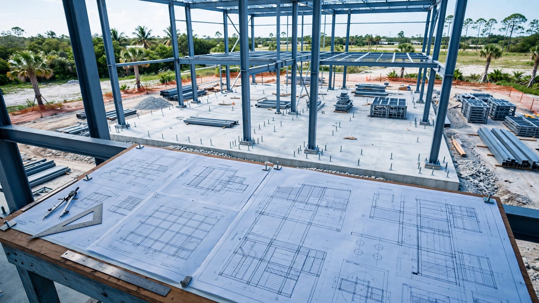
Before excavation, collect the complete construction package. Do not rely on a sales sketch or an old estimate. You need the current building dimensions, foundation plan, anchor-bolt plan, reactions, base-plate details, and any approved revisions.
A useful package should identify the building footprint, column lines, anchor-bolt locations, bolt count, diameter, projection above concrete, and required reactions at each location. Reactions are often listed in kips, and they help the foundation engineer design concrete thickness, footers, reinforcement, and connections.
Separate the building plan from foundation design
The building supplier's anchor-bolt plan shows how the steel frame connects to the concrete. It may not be the complete foundation design. A local concrete or structural engineer must review the soil, loads, site conditions, and code requirements before selecting the slab depth and foundation details.
Some suppliers provide engineered foundation drawings with their packages. Review the exact scope before ordering, including the details described in these steel building foundation and anchoring advantages. Confirm whether the drawings cover your building, location, design loads, and permit requirements.
Confirm what the kit includes
Anchor bolts, rebar, concrete, vapor retarders, footers, base trim, doors, insulation, and framed openings may be separate items. The same applies to roofing accessories. Panel profiles, fasteners, closures, ridge components, trim, and sealants should appear in the written package scope.
Review the steel building package details and exclusions with the supplier before concrete work begins. A missing component can change scheduling, access, or the foundation layout.
Match the concrete slab to the building loads
A slab may function as a finished floor, a foundation element, or both. If the steel frame transfers vertical reactions, uplift, or lateral forces through its columns and anchor rods, the concrete design becomes part of the building's structural load path.
Design footers, thickened edges, and reinforcement
The engineer's plan may call for thickened slab edges, isolated pads, grade beams, continuous footers, reinforcement, or other details. The correct arrangement depends on the kit's reactions and the site's soil and wind conditions.
Do not choose a universal slab thickness, footer width, embedment depth, bolt diameter, or bolt count from an online chart. A small agricultural building and a wide Florida structure with large openings can place very different demands on the foundation.
If you plan to reuse an existing slab, have a qualified engineer evaluate it. The review should cover concrete condition, dimensions, reinforcement, soil support, anchor locations, and the current code requirements. Cracks or a previous building layout do not prove that the slab can support a new kit.
Account for Florida conditions and permits
Florida projects require attention to wind loads, flood zones, drainage, soil conditions, setbacks, and local amendments. Coastal exposure and high-wind areas can affect the frame, anchors, connections, roof panels, and foundation.
The Florida Building Code, 8th Edition (2023), requires steel anchor rods to follow the approved construction documents. Your local building department also determines which code edition and amendments apply to the permit. Review the Florida metal building permitting guide before ordering materials or scheduling the pour.
Florida concrete provisions also include baseline requirements for ordinary slabs on ground. The cited code language lists a 3.5-inch minimum for concrete floor slabs supported directly on the ground and a 6-mil polyethylene vapor retarder with joints lapped at least 6 inches. Structural steel-building foundations may require more, and the engineer's sealed plan controls.
Control and contraction joints should follow ACI 360 or another approved standard. Concrete anchorage must follow ACI 318 as adopted by the applicable code. These provisions support the design, but they do not create a one-size-fits-all foundation.
Pre-pour anchor bolt checklist for contractors
Walk the layout with the current drawings before the concrete truck arrives. The concrete crew, steel-building supplier, surveyor, and engineer should work from the same revision.
Set the building lines and use a template
Begin with established property and building benchmarks. Confirm the building corners, centerlines, column lines, diagonals, and finished-floor elevation. A layout that is square at one corner can still be wrong if the entire footprint is shifted.
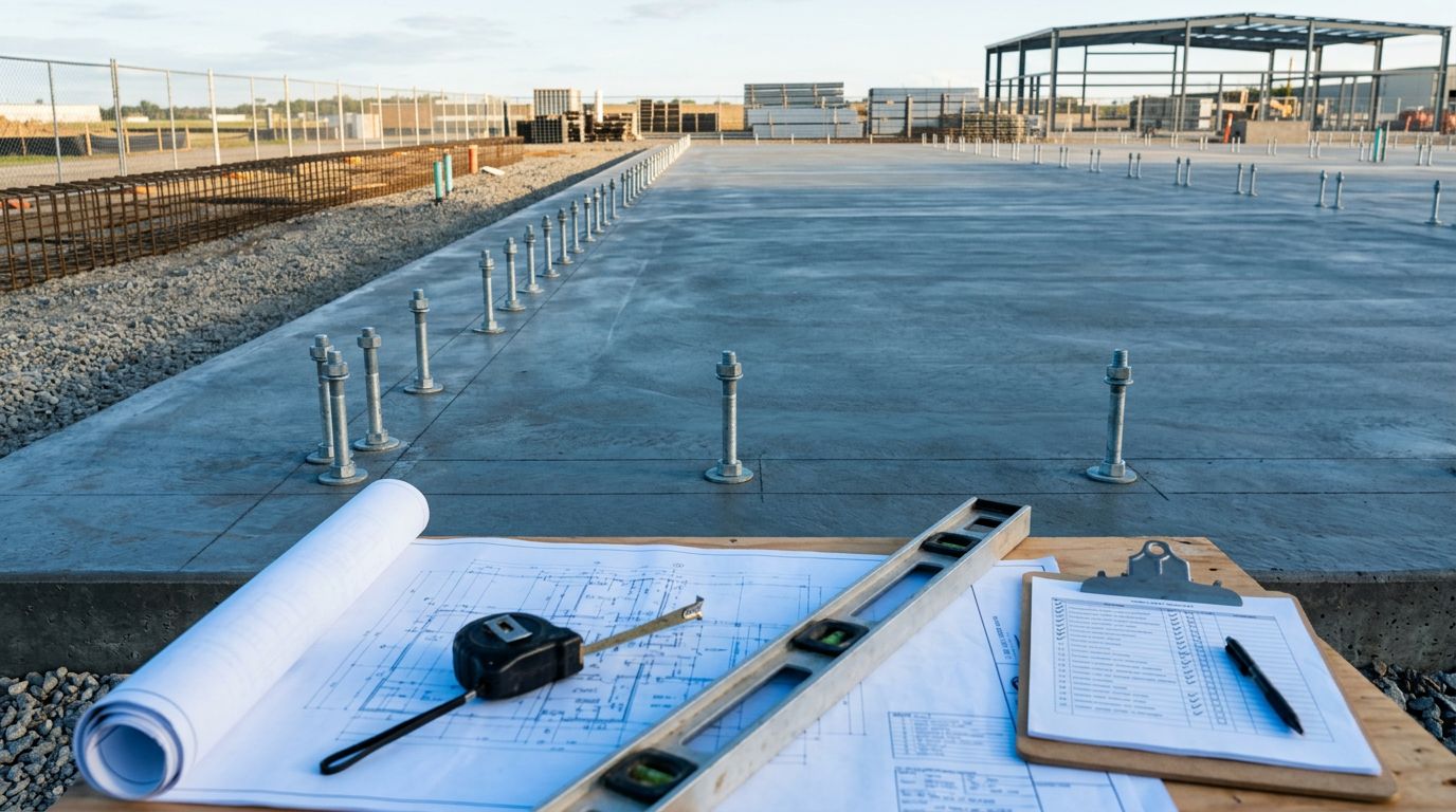
Use a rigid template or jig to hold the anchor rods in the correct pattern during the pour. The template should match the manufacturer's plan, not a field measurement taken from a base plate. Check each group of rods for spacing, orientation, and relationship to the building lines.
Keep the rods plumb and perpendicular to the concrete surface. The manufacturer's guidance commonly calls for rods to remain at approximately 90 degrees. Tie or brace them so vibration, reinforcement, workers, and concrete placement cannot move them.
Verify each rod before concrete covers it
Compare every anchor group against the plan. Record the following details before the pour:
- Confirm the location, spacing, count, and pattern at each column or frame line.
- Check the specified rod diameter, grade, length, threads, nuts, and washers.
- Measure the planned projection above the finished concrete surface.
- Confirm the finished-floor elevation and the top of each footing or thickened area.
- Check that reinforcement and sleeves do not force rods away from their planned locations.
- Protect exposed threads from concrete, mud, damaged equipment, and impact.
- Photograph the layout and record measurements before placement begins.
The threaded portion must provide full nut engagement through the connected material. Florida steel-code language also limits projection so the exposed end does not exceed the usable thread length on the rod. The manufacturer and engineer determine the correct projection for the actual base plate and connection.
Do not replace specified rods with J-hooks, L-hooks, or post-installed anchors because they are available locally. Florida code prohibits J- or L-hooks in certain prescribed concrete connections, and a steel-building kit may require a particular cast-in anchor system. Get written approval before changing any anchor detail.
Protect the layout during concrete placement
A correct layout can move during the pour if the crew does not monitor it. Assign one person to check anchor rods while concrete workers place and vibrate concrete around each group.
Inspect rods during and after the pour
Keep the template in place as long as the foundation plan allows. Check plumb, spacing, projection, and alignment after concrete reaches each anchor area. Do not use a vibrator directly against the rods or template.
Remove concrete from the threads before it hardens. Clean any splatter with a method approved for the rod and connection. Avoid bending, heating, cutting, or forcing an anchor rod. Those actions can change its strength and position.
After finishing, recheck the rods before the concrete sets. Compare them with the plan again, then document the final condition. If a rod has shifted, contact the building supplier and engineer before the concrete cures. A field fix may require an approved repair detail, not a guess made at the jobsite.
Confirm slab details and curing requirements
Verify that the subgrade, base material, reinforcement, vapor retarder, footers, joints, and elevations match the foundation drawings. A vapor retarder with poorly sealed laps, missing reinforcement, or an incorrectly placed joint can affect the finished foundation even when the rods are accurate.
Follow the specified concrete strength, curing period, and inspection requirements. Do not schedule steel erection based only on a calendar date. The engineer, inspector, or concrete testing records may require confirmation that the concrete has reached the strength stated in the construction documents.
Repeat the anchor bolt checklist before steel erection
The steel crew should receive the current construction package and the as-built anchor records. Before unloading the frame, inspect the foundation and confirm that the concrete is ready for the planned connection.
Survey location, projection, and verticality
Measure the anchor rods against the building lines, not only against adjacent rods. Check the overall footprint, column spacing, diagonals, elevation, projection, and verticality. A single rod can appear close to its neighbor while the entire building line remains out of position.
Inspect the threads, nuts, washers, base plates, and concrete around each connection. Confirm that the nuts can fully engage the threads and that the base plates sit at the specified elevation. Use grout only when the drawings or engineer call for it.
A useful pre-erection record includes dated photographs, survey measurements, concrete test results, approved repairs, and the drawing revision used for the inspection. Keep it with the project documents.
Stop when the frame does not fit
Never force a base plate over a misplaced rod. Do not torch-cut a rod, bend it with a pipe, enlarge a base-plate hole, or weld an improvised bracket without written approval from the responsible engineer and building supplier.
If the fit is wrong, stop that connection and report the measurement. The supplier may issue a correction detail, while the engineer determines whether the concrete, reinforcement, and anchor capacity remain acceptable.
Use the supplier's steel building installation manuals for anchor placement, frame assembly, door and window spacing, and panel layout. The construction package should control the work at the site.
Mistakes that cause slab and anchor problems
Many foundation corrections begin with an assumption that seemed harmless during planning. Watch for these common errors:
- Ordering a kit before confirming whether anchor bolts and foundation drawings are included.
- Pouring a standard slab without reviewing the building reactions and soil conditions.
- Setting rods from a base plate, sales drawing, or previous building instead of the current anchor plan.
- Skipping the template and trusting a tape measure during concrete placement.
- Measuring rod spacing without checking the building lines, diagonals, and finished elevation.
- Allowing concrete to cover dirty or damaged threads.
- Changing rod type, diameter, embedment, or projection without engineer approval.
- Scheduling steel erection before checking concrete strength and as-built anchor locations.
- Ignoring flood, wind, drainage, or inspection requirements in the local jurisdiction.
Roof panels and trim should also be coordinated with the kit drawings. Wall openings, eave heights, framed doors, overhangs, and roof geometry affect panel quantities and flashing details, even though they don't determine the anchor layout. Confirm those materials early so the foundation, frame, and enclosure schedules stay aligned.
Conclusion
A steel building foundation begins with accurate documents, not a generic slab formula. The manufacturer's anchor-bolt plan identifies the connection layout, while a qualified engineer designs the concrete foundation around the building reactions and Florida site conditions.
Use the anchor bolt checklist before excavation, during the pre-pour inspection, immediately after placement, and again before steel erection. Accurate lines, braced rods, correct projection, clean threads, documented measurements, and approved corrections give the frame a sound connection to the slab.
Share Our Metal Roofing News Articles
Related Posts