Florida Gutter Sizing for Metal Roofs: A Practical Guide
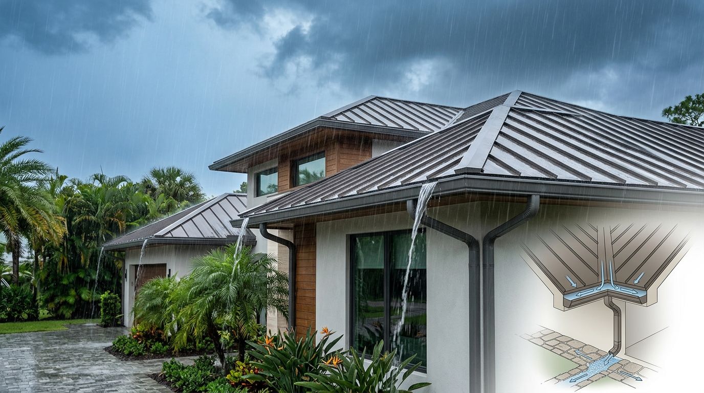
A metal roof can move a large volume of water to the eaves in a short time, especially during a Florida downpour. An undersized gutter may overflow at valleys, stain the fascia, and discharge water beside the foundation.
For accurate Florida gutter sizing , calculate the roof drainage area, use the local design rainfall intensity, and match each gutter and downspout to the resulting flow. Metal roofing doesn't automatically require a special code multiplier, but its fast sheet flow makes layout, slope, outlet spacing, and edge details less forgiving. Start with the rainfall and roof area.
Florida gutter sizing starts with rainfall
Gutters collect runoff from a defined roof area. Their capacity must handle the flow produced by the local design storm, not an average afternoon shower.
Many Florida drainage calculations use the 100-year, one-hour rainfall intensity for the project location. The correct number depends on the property's latitude and longitude. Contractors preparing permit drawings may use NOAA Atlas 14 rainfall data, then confirm the required design basis with the local building department or engineer.
Rainfall intensity varies across the state. A design value near 8 inches per hour may apply in some South Florida drainage calculations, while another county may require a different figure. Never use 8 inches per hour as a statewide default.
Metal roof runoff needs practical attention
Florida code does not generally add a runoff factor solely because the roof uses steel or aluminum panels. The main inputs remain:
- The roof's horizontal drainage area
- The local rainfall intensity
- The gutter's shape, width, depth, and slope
- The number, size, and location of downspouts
Still, metal panels shed water quickly. Granular roofing and other textured surfaces may slow sheet flow slightly, while smooth metal sends water toward the eave with little resistance. Valleys and long unbroken eaves can concentrate that flow at one point.
That concentration is why a system that appears adequate on a small shingle roof may overflow when installed on a large metal roof with two valleys feeding one gutter.
Measure the drainage area correctly
Use the horizontal projected area of each roof section, rather than adding the sloped surface measurements. Divide the roof wherever water changes direction or reaches a different gutter.
For example, a gable roof with two equal slopes may send each slope to a separate eave. A hip roof may send runoff to several eaves, while a valley can combine two roof sections into one concentrated drainage zone.
Measure each zone separately. Then identify which gutter receives that water and where the downspouts will carry it.
Calculate the required roof flow
The basic roof drainage formula is:
Required flow in gallons per minute (gpm) = roof area in square feet x rainfall intensity in inches per hour / 96.23
This formula gives the approximate water flow for a roof drainage zone. It does not select the gutter by itself. You still need to compare the result with the gutter and downspout capacity.
Use the local design intensity
Ask the authority having jurisdiction, or AHJ, which rainfall source and code edition apply to the permit. A contractor may also need a licensed design professional for larger commercial roofs, internal drains, storm piping, or unusual drainage conditions.
For planning purposes, use the approved local intensity rather than a generic national number. A difference between 5 inches per hour and 8 inches per hour changes the required capacity by 60 percent.
The roof material doesn't change that rainfall calculation. However, fast runoff can expose weak details sooner, especially where the gutter has little slope or a long run carries flow toward one outlet.
Divide the roof into drainage zones
Don't calculate an entire building as one roof area unless every gallon reaches one connected drainage system. Instead:
- Measure the horizontal area that drains to each gutter section.
- Add roof areas that combine at a valley or shared eave.
- Calculate the flow for every section.
- Divide each section between planned outlets.
- Compare the flow in each gutter segment with its rated capacity.
A gutter's capacity depends on the water depth and the point where the outlet is located. A long gutter with one downspout may carry nearly the full accumulated flow near that outlet, even if the building has several roof slopes.
Step-by-step example for a Florida metal roof
Suppose a metal-roofed home has 2,000 square feet of horizontal drainage area . The local design intensity for the project is 8 inches per hour .
The calculation is:
2,000 x 8 / 96.23 = approximately 166 gpm
That is the design flow for the entire drainage area. It is not a recommendation to place one 5-inch gutter around the entire roof. A single gutter run receiving all 166 gpm would need a capacity greater than that amount, along with properly sized outlets and downspouts.
Split the flow before selecting components
Assume the roof layout allows four separate drainage zones of 500 square feet each. The flow for each zone is:
500 x 8 / 96.23 = approximately 41.6 gpm
Each zone now sends about 41.6 gpm to its assigned gutter and outlet. If a zone has two outlets, each outlet receives approximately 20.8 gpm, provided the gutter slope and outlet placement divide the water evenly.
This is why outlet placement matters as much as nominal gutter size. Splitting a large roof into shorter drainage zones can reduce the flow carried by each gutter section.
The design still needs a downspout with a rated capacity at least equal to its assigned flow. Check the gutter manufacturer's data for the complete assembly, including the outlet, downspout profile, bends, and discharge connection.
A 2,000-square-foot roof at an 8-inch-per-hour design intensity produces about 166 gpm. A 5-inch gutter rated at 74 gpm cannot carry that entire flow in one drainage zone.
Choose gutter capacity, slope, and profile
The Florida Building Code, Plumbing, Chapter 11, addresses storm drainage. Section 1106 and Table 1106.6 provide gutter capacity values based on gutter dimensions and slope.
Selected table values include:
| Gutter configuration | Slope | Listed capacity |
|---|---|---|
| 1.5 x 2.5 inches | 1/4 inch per foot | 26 gpm |
| 1.5 x 2.5 inches | 1/2 inch per foot | 40 gpm |
| 4-inch gutter | 1/8 inch per foot | 39 gpm |
| 2.25 x 3 inches | 1/4 inch per foot | 55 gpm |
| 2.25 x 3 inches | 1/2 inch per foot | 87 gpm |
| 5-inch gutter | 1/8 inch per foot | 74 gpm |
| 4 x 2.5 inches | 1/4 inch per foot | 106 gpm |
These values show why Florida gutter sizing can't rely on the gutter's width alone. Shape, depth, and slope all affect how much water the gutter can carry.
Don't treat 5-inch gutters as a universal answer
A 5-inch gutter at 1/8 inch per foot has a listed capacity of 74 gpm in the table above. That may work for a smaller drainage zone, but it may fail on a long eave, a steep metal roof, or a valley carrying concentrated runoff.
A larger gutter profile may offer more capacity, but it still needs the correct slope and outlet design. A deep commercial gutter with a small outlet can remain a restriction at the transition point.
Check the actual gutter profile, not only the trade name. Confirm the inside dimensions, minimum slope, end conditions, outlet size, and hanger spacing before ordering material.
Size downspouts by assigned flow
Downspouts must remove water from the gutter faster than the gutter receives it. Their capacity depends on more than the width printed in a catalog. The downspout shape, height, bends, outlet opening, connection to storm piping, and discharge conditions can all affect performance.
Use this process for each gutter section:
- Calculate the total flow entering the section.
- Decide how many outlets will serve that section.
- Divide the flow between outlets based on the actual layout.
- Select a downspout and outlet assembly with a rated capacity above the assigned flow.
- Recheck the gutter segment nearest each outlet.
A single downspout near the end of a long run may leave the far end vulnerable to overflow. Adding an outlet near the center, valley, or high-flow area can reduce the amount of water moving through the gutter.
Place outlets near valleys and long eaves
Valleys deserve special attention because two roof planes may send water into one narrow area. Install an outlet or downspout close enough to the valley to control the concentrated flow, while following the gutter manufacturer's requirements for outlet spacing.
For larger drainage systems, a University of Florida facilities standard uses one downspout per 50 feet of gutter where possible and conductor heads every 40 feet on downspouts to admit air. Those figures are useful design references, but they don't replace the adopted code, manufacturer data, or project-specific calculations.
Downspouts also need a safe discharge point. Use splash blocks, extensions, or an approved underground drainage connection to move water away from the foundation. Never let a high-volume downspout empty directly beside a footing or crawlspace wall.
Match the gutter to the metal roof edge
A gutter only works when the eave detail directs water into it. Metal panels, underlayment, eave trim, drip edges, fascia, and gutter hangers must fit together without creating a path behind the gutter.
Review the panel profile before choosing the edge trim. Mid Florida Metal Roofing Supply provides a metal roof eave drip edge guide that addresses panel type, fascia height, gutter geometry, fasteners, laps, and sealed joints.
Keep runoff inside the gutter
The eave trim should project water into the gutter rather than behind it. A short fascia leg, incorrect bend, or excessive panel overhang can send runoff behind the gutter during wind-driven rain.
Standing seam and exposed-fastener panels may use different trim details. Follow the approved panel system and manufacturer's installation instructions. Confirm the drip edge, eave trim, closure, and gutter position before the roof panels are installed.
Use compatible materials and secure hangers
Florida's residential code requires exterior gutters and leaders to use metal or approved plastic suitable for outdoor exposure. Joints need appropriate laps, soldering, or sealant, and installers must use secure, compatible, corrosion-resistant fasteners.
Metal roofs near the coast face salt exposure, so material compatibility matters. Avoid combinations that promote galvanic corrosion. Use the hanger type and spacing specified for the gutter system, and attach hangers to sound fascia or approved structural blocking.
Check Florida code and local AHJ requirements
The Florida Building Code connects roof drainage design to the Florida Plumbing Code and ASCE 7, Chapter 8. Local enforcement still controls how those requirements apply to a particular project.
Before installation or permitting, verify:
- The code edition adopted by the local jurisdiction at the permit date
- The required design rainfall intensity
- Whether the gutter work belongs on the roofing permit or needs separate approval
- Whether the AHJ requires drainage calculations or a roof plan
- How downspouts must discharge on the property
- Whether stormwater connections require separate approval
- Whether the property falls within a High-Velocity Hurricane Zone
- Which product approvals and installation details apply to the roof edge and trim
The Florida Residential Code also addresses overflow protection. Where another overflow drainage method isn't provided, overflow scuppers may be required. The code places them 2 to 4 inches above the finished roof covering and as close as practical to the vertical leaders or downspouts.
Commercial buildings often require a more detailed system. Internal roof drains, primary and secondary drainage, conductor heads, overflow scuppers, and storm piping may need engineered calculations and plan review.
Field checks before the first rain
A short review can catch problems before the gutter system is fastened permanently.
Confirm that:
- Each roof area drains to the intended gutter section.
- Valleys don't discharge beside or over the gutter end.
- Gutter slope follows the approved installation detail.
- Outlet openings match the selected downspouts.
- Long runs have enough outlets for the calculated flow.
- Hangers attach to solid backing and use compatible fasteners.
- Eave trim directs water into the gutter.
- End caps and laps are sealed as specified.
- Downspouts empty onto splash blocks, extensions, or approved drains.
- Overflow protection meets the adopted code where required.
For a contractor, keep the roof plan, calculations, product data, and trim details with the project records. For a homeowner, ask for the drainage zones and outlet locations before approving the installation.
Conclusion
Reliable Florida gutter sizing starts with the roof area and local rainfall intensity. Calculate each drainage zone, divide concentrated flow between suitable outlets, and compare gutter capacity with the actual design demand.
A metal roof doesn't automatically require a special runoff multiplier, but its fast, concentrated flow makes poor eave details and undersized outlets show up quickly. Match the gutter, downspouts, drip edge, and discharge plan to the roof system, then verify the current Florida code and AHJ requirements before work begins.
Share Our Metal Roofing News Articles
Related Posts